
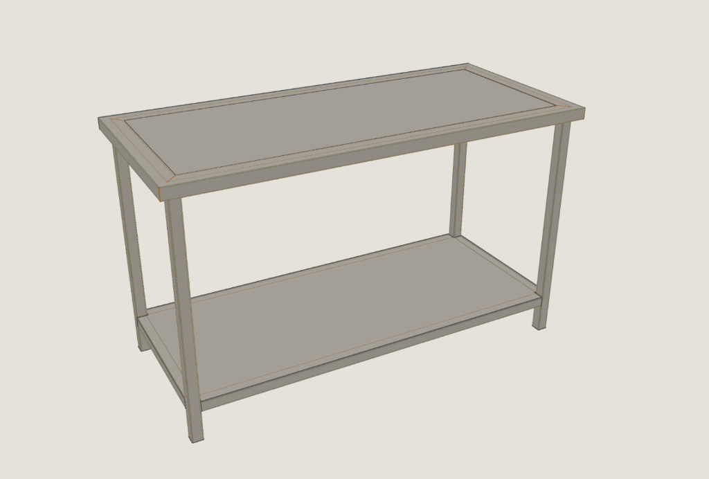
A few weeks ago I wrote about why I started a semantic fabrication kernel. Since then I have built quite a bit more of it. You can try the current version at kernel.kubuz.net.
The reactions to that first piece were useful. They forced me to explain something I had not explained very well: why build a geometry kernel in the first place?
The answer is simpler than the word semantic makes it sound. I wanted configurators for products that are actually built in ordinary workshops. Folded sheet metal, profiles, mitred ends, holes, pockets and simple assemblies. Real product definitions, nothing exotic. And I wanted those products to update while someone was configuring them. That turned out to be harder than I expected.
The two usual routes
Inventor, SolidWorks and the other CAD systems can model all of this. They are far more capable than anything I am building. Once that geometry has to sit inside a web configurator, there are usually two routes. You automate CAD on a server, or you bring a general-purpose geometry kernel into the browser through WebAssembly.
Both make sense. For the products I was working on, both felt like a lot of machinery. I was not using a full CAD suite for this work.
I needed a plate that could fold a couple of times, a profile cut at an angle, a hole that still knew it was a hole, and a few parts placed together. It all had to evaluate fast enough to stay inside the interaction loop of a configurator.
So I asked how small that geometry engine could be if it only understood the fabrication operations I actually needed. That was the start of the kernel.
A small fabrication language
The first versions were very limited. A sheet had a face, an edge could become a flange, and a profile had a section and a length. Once that worked, the vocabulary grew. Flanges gained angles and partial lengths. Hems appeared. Profiles gained mitred ends and machining. Rolls and transitions followed, and parts could be placed together into assemblies.
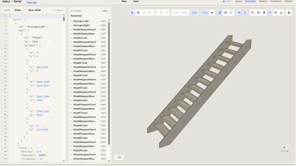
Because the kernel runs in the browser through WebAssembly, changing a parameter does not mean opening a CAD document somewhere else and waiting for it to rebuild. The programme evaluates again.
That was the first important result. The second surprised me more. The input was not a mesh, and it was not a pile of anonymous faces. It still contained manufacturing meaning. A flange was still a flange, a hem was still a hem, and a mitred profile end was still a mitred profile end.
{
  "op": "flange",
  "on": "Top",
  "edge": "e3",
  "outside": 40,
  "angleDeg": 90
}
The interesting part is not the JSON format. It is the word flange. That word has a defined meaning. The kernel knows what to do with it: how the operation affects the developed sheet, how it folds, and which geometry should come out.
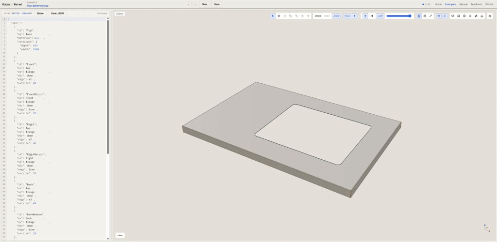
That is where semantic started to make sense to me. JSON is only a convenient format, and the kernel does not understand the complete product. The programme still says what kind of fabrication operation something is, instead of only describing the final shape.
Where the kernel stops
Building it also made the boundary clearer.
I still want a model that knows what parts mean and how they relate to one another. I wrote about that in geometry is not the product model. That knowledge does not all belong inside the geometry kernel.
A product may know that a part is the rear rail of a table, that its length depends on the table width, that a brace is required above a certain span, and that an option adds another component. That is product knowledge. It belongs in the CPQ or the product model.
By the time the geometry kernel sees the part, the question is concrete. The product model might say that this is the rear rail of the table. The fabrication programme says that it is an RHS 40 × 40 × 2, 842 mm long, with this end cut and these holes. The kernel turns that description into geometry.
The same distinction shows up on a single profile. A mitred end is still a mitred end in the programme, not only a solid with a slanted face.
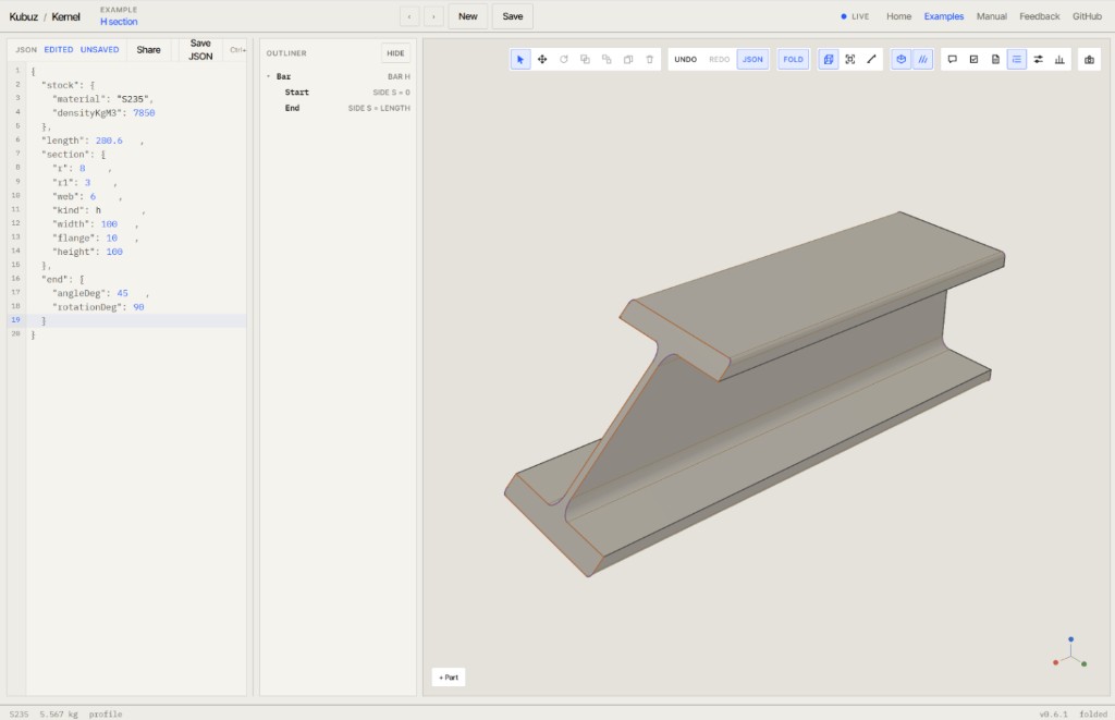
The product model describes the product. The fabrication programme describes how its parts are made. The kernel evaluates that programme, and geometry is one of the results.
I do not want geometry to be the product model. I want it generated from a more meaningful description.
Without a CAD rebuild
One fair comparison is DriveWorks or KBEWorks. Those tools already connect product rules with CAD, and they solve real problems. This experiment takes a different route.
Instead of using CAD as the execution engine behind the configurator, I am asking whether some products can skip that step during interactive configuration. The flow becomes configuration, then a fabrication programme, then the kernel, then a result. The other flow is configuration, then a CAD model, then a rebuild, then a result.
There is no CAD application running in the background, and no CAD document that has to open, rebuild and save. The kernel does not need to support everything an engineer might ever want to model. It only has to understand a smaller set of fabrication operations.
That restriction is the whole idea. Most companies that use CAD only use a limited part of it, often something like 10 to 20 percent of what the software can do.
The more I build, the more interesting that trade-off becomes. Profiles, angled cuts, machining, rolls, transitions and larger assemblies now fit in the same small language.
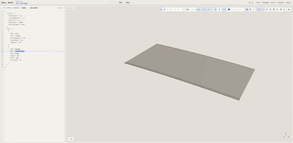
There will be a point where this stops being the right tool and full CAD is the better choice. I do not know yet where that point is.
More than the 3D view
If this only produced parameter-driven meshes, it would just be a 3D configurator. The 3D view is one output. The same programme can also produce the developed sheet, bend information, material usage and other manufacturing measurements.
More recently I have started letting the geometry answer simple questions about itself.
- Do two parts pass through each other?
- Is there a gap where two manufactured ends are supposed to meet?
- Does a folded sheet collide with itself?
- Are parts actually touching the way the programme expects?
These are geometry checks, not engineering approval. They are where it starts to get interesting. At first the flow was mostly one way: a programme in, geometry out. It is starting to become a loop. The programme goes in, geometry comes out, and the checks come back. Software can reason about the result, not only display it.
What an agent can say
This is also why I still think the structured programme can be useful for AI. I would put that differently now. A language model reading JSON easily is not the reason. JSON is just a convenient format.
What matters is that the language is small and explicit. A model does not need to know how to calculate a correct sheet-metal development. It can say: add a flange here. The kernel stays responsible for the geometry. The model works with intent, and the kernel stays deterministic.
After evaluation, the result can be checked again. That gives an agent a loop it can actually use: change the programme, evaluate it, inspect the result, and correct it.
Other engineering work is moving in a similar direction, with a smaller structured model for intent and deterministic software for the engineering output. I do not think the important idea is that engineering should suddenly be written in JSON. The more interesting pattern is a small domain language for intent, and a deterministic engine that turns that into engineering output. I want to see how far that pattern can go for mechanical fabrication.
SysML v2 helped me place the layers as well. A system model can hold requirements, relationships and functions. GD&T can add another kind of meaning, by describing allowable variation. Neither replaces something that can turn fabrication intent into geometry. They solve different problems, and they can sit next to each other.
How far this can go
The split is clearer now that more of the kernel exists. A product model sits above it. A fabrication programme sits between the product and the geometry. A small engine understands that programme well enough to turn it into geometry and manufacturing feedback.
In short: product meaning, then fabrication intent, then geometry.
The original reason was practical. I wanted light fabrication geometry directly in the browser. The semantic layer came into focus afterwards, because that small fabrication language turned out to be a useful boundary between product knowledge and geometry. The AI angle came after that, because a small explicit language is easier for a software agent than arbitrary geometry.
The question I care about is still open. How much configurable fabrication can be described this way before you really need full CAD?
I do not know the answer yet. I have built enough of the kernel to think the question is worth pursuing. The next step is designing with it.